rosco01 Posted February 26, 2015 Author Report Share Posted February 26, 2015 Ok just a shorty - four pix.... as promised. Here's a 1/32 Cooper slot car pic you don't see very often.... Spent this evening getting the two halves ready for re-joining. Painted the intake manifold and started building the "light putty" to marry up the matching faces of the main and tail body sections. Pix aren't a true perspective - camera angles are wrong and the body halves aren't yet sitting where I want them before bonding them. I painted around the intakes because I won't be able to get in once the two portions are joined. I have yet to make a final decision on just how much intake will be seen as well..... If I reduce the cover opening - it will be with light putty... stuff is amazing.. but, and I hope it's just not my tube..... it absolutely hates Tamiya primer... won't harden properly and seems to come unstuck without too much prodding around... so, I'm not that much in favor for using it on a body which has been primed.... I did try wiping it with the recommended Tamiya thinner... to no avail. The pic of the intakes with cover over them is a little deceptive - that "black" also covers the body below them... so, there's no "hole" to be filled.. just an over-exhuberant use of the Floquil engine black applied with thin brush. You can see the brass tail cover frame and the roll bar - I believe I have these correct.. not sure on the roll bar - they vary a bit. I am now considering drilling and fitting the tail section tie-downs... not a huge job - but will give the model a bit more "3-D".. as opposed to the molded parts. Final 3 pix... Hope to have the body back on one piece by tomorrow night.... frats, Rosco Quote Link to comment Share on other sites More sharing options...
Wobble Posted February 26, 2015 Report Share Posted February 26, 2015 (edited) Looking great there Rosco... Not that the original rear springs were bad, but these are just better... Ross, I found a BIC lighter yesterday and opened it up to have a look at the spring you guys are talking about and you are using. Now I'm even more impressed with your work! Body work looks impressive too. Edited February 26, 2015 by Wobble Quote Link to comment Share on other sites More sharing options...
Ember Posted February 26, 2015 Report Share Posted February 26, 2015 I have yet to make a final decision on just how much intake will be seen as well..... If I reduce the cover opening - it will be with light putty... stuff is amazing.. but, and I hope it's just not my tube..... it absolutely hates Tamiya primer... won't harden properly and seems to come unstuck without too much prodding around... so, I'm not that much in favor for using it on a body which has been primed.... I did try wiping it with the recommended Tamiya thinner... to no avail. I've not had any such problem with it. I used it to rebuild some areas when I redid the chassis of my first shell. At the moment I'm still using Tamiya primer. Absolutely no issues with it. The putty does cure better in bright sunlight than in artificial light. And sometimes it has a bit of a sticky finish, but other times it does not. Tamiya primer used both over and under it with no issue. Quote Computers. They'll never catch on. Tiny Tyers Targa - The build saga continues - Aging wood - A recipe for staining wood - Don't take a fence - Step by step paling fence - An old shed for my new cars - Wooden garage under construction Link to comment Share on other sites More sharing options...
rosco01 Posted February 26, 2015 Author Report Share Posted February 26, 2015 Thanks, Bram - the long, thin spring is the one to use - and 1/16" brass tube is a great fit inside it - then there's the brass rod which will fit inside that. Ember, maybe there was some contamination issue in where I had problems with it. Not long after getting the bodies - I wanted to trench out the body joins... and went a bit deep. Before I could get my hands on the light putty, I tried a number of different ones from my LHS - all of them failures - the "recommended" one was a total failure - it simply "chalked" out when I tried to re-groove the original lines... so, benefit of the doubt - contamination. I'll know more about the tube of LP when I attack the other body, save being cut in half and primed in Tamiya fine primer - it's had nothing done to it. Had a think about that intake cover last night ... I'm going to close it up just a tad more.... with just the lower section of trumpets visible from side on... #2 will (has to) get the same treatment - but #3 won't (previously seen uncut white body in this thread). Post more up tonight - hope to have it back in one piece by COW tonight......... (close of work). sounds like a bit of BULL to me.... frats, Rosco Quote Link to comment Share on other sites More sharing options...
Ember Posted February 27, 2015 Report Share Posted February 27, 2015 If you're looking to close up a gap, you might find it easier if you put a bit of tape over the hole from the rear. I used two piece of duct tape (the tape for all occasions) stuck together, smaller piece in the middle of a larger piece, which was then stuck to the inside wall of the shell. It just made it easier to control the amount of putty I applied. The small piece was simply to give me a non-sticky surface over the hole. Quote Computers. They'll never catch on. Tiny Tyers Targa - The build saga continues - Aging wood - A recipe for staining wood - Don't take a fence - Step by step paling fence - An old shed for my new cars - Wooden garage under construction Link to comment Share on other sites More sharing options...
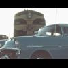
rosco01 Posted February 27, 2015 Author Report Share Posted February 27, 2015 (edited) Thanks Ember, got to this too late. Used the conventional layer build method. Three in total. I might have a dud batch of this putty - today, in as dark an area as I could work in - I pushed a little bit out onto the end of a tiny spatula... put the lid on - and just as I was spreading it into the spot (less than 15 seconds later) - it went off.... rock solid on the spatula... but the little bit I did get onto the model was good... Next shot - no problem - and had a good minute to work before it started to gel. Third shot - same as first - and it fell out of the hole.... Fourth attempt - better.. but not great... left it there and put it in the bright sunshine for a good two minutes. This stuff is simply amazing to file or sand... and it's permanent rock hard. So, continuing on the build - I spent this morning setting up the two body halves.... then ran a drop of Zap CA medium to the joint on each side to hold it. Once it set, I then used some milliput to build and strengthen the joint (first time used - bit of a battle until I learned that it can be made "sticky" simply by wetting the spatula with a drop of water). I also keyed out where the front mounting screw will be located - and mixed up another small dollop of Milliput - had a terrible time trying to get it to stick to the underside of the clean and etched body - and gave up after about 30 minutes... leaving a small "block" which is perfectly molded to the underside of the body. I then started work on rubbing down the model - and setting final height with again - Light Putty. Have filled that intake air cover to just above the original height - and as intended - my intakes are half visible. When the Milliput had almost set - it didn't take much to knock it away from the body. Cleaned everything up again and simply put a drop of Zap CA onto the Milliput... and - the block is now rigidly set to the body... not sure where I go from here - but the body now has a rock-solid mount.... just need to build up or space the chassis when I come to that bit. I have left about 1.5 - 2mm of "float" for the body to slide around on at the rear - it meant grinding out a bit more of the exhaust port in the body - then re-filling it with Light Putty after to fill any unnecessary extra clearance.. After tea, I washed the entire body with warm soapy water, dried it and took it outside for another couple of light coats of Tamiya primer... I'll leave it now for a few days and go back to the chassis... Work will start on the wheel inserts tomorrow - along with spraying some clear gloss over the exposed chassis parts... the grey looks a treat.. and I believe it's close to the Cooper grey used on the chassis of these little cars. So folk - getting there... lots to go yet - still a few "plans" yet to think seriously about... Should have a pic up of the body tomorrow night. Oh - another little job done - the front... intake - ground out the meat and left the aperture. I will reinforce this with some brass rod and CA... and build in the radiator screen well back where it belongs. The 1964 Bill Patterson car I am modeling had two vertical supports in the opening - that might serve well as further reinforcement... I like openings to be "open"... This is the pic I am using as reference... would like a larger/more detailed one, if anyone knows where there are some. There is a little opening in this T-53 just forward of the windscreen.. so, guess I better set to and plan out how that is to be done. Also note what appears to be a black steering wheel... and the modern racing helmet - guess he wore goggles - there's no visible shield flipped up. Wheels are black, rims alloy - suits me. Note the two vertical vane supports in the cowl... Shocking pic.. but it's all I've got so far on this car. More tomorrow. frats, Rosco Edited February 27, 2015 by rosco01 Quote Link to comment Share on other sites More sharing options...
Ember Posted February 27, 2015 Report Share Posted February 27, 2015 Hmmmm... PM me your address Ross, I'll send you my spare tube. It'll be ages before I need it. Quote Computers. They'll never catch on. Tiny Tyers Targa - The build saga continues - Aging wood - A recipe for staining wood - Don't take a fence - Step by step paling fence - An old shed for my new cars - Wooden garage under construction Link to comment Share on other sites More sharing options...
rosco01 Posted February 28, 2015 Author Report Share Posted February 28, 2015 Again, young lady - thank you for your ever-so-kind thoughts. Rosco is a bit of a stubborn mule, I'm afraid - I'm not giving up on the putty I waited so long for yet.... I might squirt a good portion out and bin it - then find out if the nice and soft feeling stuff from about the middle of the tube is any better. But, if I need help - I'll sure take up your kind offer in the life-raft... Body is primed awaiting more filler and sanding out scratches... Chassis is clear coated and drying - waiting for detailing with the hand brush - then I can assemble it again and put it aside.... that will be a milestone in the project. Still very concerned about Bill Patterson's weight... well, girth actually - I am struggling to believe that any driver will find it's way atop the motor... and yet the remnants of which will still look like a driver - and not a head on a great block of tin...... guess I'll know more when I trial fit hiim... Probably start on the dash first... then I can get a feel for where he is going to sit behind it. I will keep the dash on my little model up high - where pix of the proto-type have it... not where Scalextric put it down low.. so, that will probably buy me some height for the driver..... My understanding/observation is that the centre of the driver's helmet is along the line of the crown of he tail ... my roll-bar (not on Bill's car in 1964, but required for proxy rules) will be above the top of the helmet..... that's as far as my thinking has got on driver position... I intend now to "split" the windscreen - three portions... the front section which was fitted to the lifting front and the two sides which were fitted to the centre body. There is a small aluminium plate fitted to the front section which overlaps and centers the two sides.... I intend to go that far in detail... but not much further... this is my plan. No other work done today - had a yard cleanup/lawn mowing (dust bowl, actually) day... and the leaves are beginning to annoy the heck out of me.... don't they know it's not Autumn until tomorrow.... blasted Plain trees we have each side of this street - and the biggest wind-blown leaves anyone could imagine....grrrrrr Hope to have some more to post up tomorrow night. frats, Rosco Quote Link to comment Share on other sites More sharing options...
rosco01 Posted March 1, 2015 Author Report Share Posted March 1, 2015 (edited) Ok - by my absence to this thread yesterday - you can probably appreciate I'm in a bit of strife.... well, will only make mention of model related issues here for all intents and purposes. The chassis and vehicle body are now well matched, the chassis has been sprayed grey and the clear coat added. Work on filling the body continues (does it ever end?). I will "never" trench out any join lines again - other than removing molding flaws - it's been a nightmare trying to get straight lines back in joins when you have had to use filler/putty to correct errant rips.... The "blob" has been removed from the nose and work is under way on making a recessed radiator and vane supports for the aperture. The vehicle body has been taken to with gusto to remove excess material, I am at the point where any further removal could be perilous in racing (read later about poor Bill's lap-band surgery and subsequent "drawn, quartering and de-capitation"). The body/chassis mount has been formed up using Milliput in three sessions and glued in position - the hole has been drilled but yet to be tapped for the mount screw. The dash/binacle insert has been trimmed down so that it is a neat fit within the cockpit surround. A small amount to form a recessed ledge has been left to allow it to be c/a'd in place. The gauges have all been drilled out in preparation for their "aquadhere" inserts and black paint. Steering wheel shaft has been made from brass rod. I am now going to fabricate my own steering wheel - the one supplied (which Bill no longer has between his hands) was far too small and without a centre. I intend to make the rim up from 0.8mm brass rod and the spokes from brass plate. The combination should assist in keeping the driver within the model - we don't want another Timmy Mayer (I do hope this does not offend) repeat at Longford, Tasmania in 1964. Now the "tizzy" bit.... driver - I'm stuck.... really fast here, and am seeking direction.... Poor Bill Patterson has been "gutted"... there's naff all left of him. With the body mounted to the chassis, and the dash sitting in place - I was able, for the first time to trial fit the body. I might point out here, that originally, I had the motor position about 2mm proud of the sides of the body - it is now flush with those sides... I can't fathom any realistic method of getting it down lower - and not have the body visibly sitting above the chassis rails... At first attempt to fit him, he looked like a traveling mechanic perched high up behind the driver... I trimmed and trimmed... Jenny Craig would have been proud of me... and have reached the point where poor Bill is just shoulders, and two paper thin arms. I could not get him down far enough so that his head was centre-line with the top of the canopy (as in the pix I have been using) - so, I drilled through his neck and into the head then fitted a brass rod. I then set about creating Gladstone Small and Bill began a series of "shrugged" descents.... poor bloke looks like he's in trouble with the missus at present.... really ducking for cover.... So folk - in your models of these tiny little half-tonners - how much of the body have you left? I'm putting this part of my build aside whilst i focus back on other items... but my mind is really stalled on how to better fit Bill into his cockpit. frats, Rosco Edited March 1, 2015 by rosco01 Quote Link to comment Share on other sites More sharing options...
rosco01 Posted March 2, 2015 Author Report Share Posted March 2, 2015 Yes, another day pounding away on the building desk whilst more fortunate persons than I get to go to vocational work, meet people on trains, and mingle with the metropolis.... I expect most of you can't appreciate just how much toil is involved in being forced to stay at home and work, work, work... so, be grateful you aren't inflicted with my plight..... Driver body... arrrrgggghhhhh! Went out and availed myself with a wallet-full of purchased options to make a better presence of Bill in his Cooper.... all went down the gurgler and I'm again where I was late last night.. well, at least now I have glued his head on and am comfortable with the line-of-sight he is taking when seated on the motor... I wanted to make up the steering wheel and complete the radiator and vanes today.... nup - spent all of it with Bill.... he and I are having a "tiff" at present... he hates me - and I'm not going to send him a Christmas card this year.... If the peer verdict is that he is ok - I'll do a lot of work to adorn his cabin... with a firewall and portion of a seat behind him and some "cunning plan" to incorporate something to cover/paint the motor.. along with some perception of depth from his missing chest down.... I gave up with my plan to keep the chassis rails parallel with the body - and have now opted to build up the wheel-arch at the rear... by about 1.5mm. This has afforded Bill to sit a little lower.... the lift in vehicle body height is almost un-noticeable... but 2 mm was.... so, 1.5 mm it ended up being. I hand painted the four springs in situ - I forgot how well black paint sticks to things you don't want to touch - and how blasted hard it is to apply it to things you do... job done, with only a couple of stray nudges..... oh, by the way - don't try and remove any mishaps with Tamiya thinner - even though I was ever so careful with the gentle wipe and lift.... I now have my Protec 1K etch showing in want of more primer and clear coats.... grrrrrrr See, told you - a "nice" day at work is no comparison to the toils one has to endure in scratch-building.... I also managed to complete the body post mount - and tap it out with a 10 BA counter-sunk screw.. the body (not driver's) is a floppy fit on the chassis - and centres itself when jiggled around....so, one job done and I can score a line through it on the project sheet.... Another day tomorrow.. will wait until I hear back on Bill's position... hope to have the radiator/vanes and steering wheel completed by this time tomorrow night... watch this space... Pix... Again, this is what I'm aiming for.. frats, Rosco Quote Link to comment Share on other sites More sharing options...
kalbfellp Posted March 2, 2015 Report Share Posted March 2, 2015 Bill appears to be sitting much higher in this race photo. Quote Phil https://www.hobartminiaturecarclub.com/ Email Link to comment Share on other sites More sharing options...
Wobble Posted March 2, 2015 Report Share Posted March 2, 2015 (edited) Ross (edit - ignore the photos of the T51, my mistake) I think you've got to add a bit of girth to Bill as well. Seems to me 1/2 the helmet should be above the rear body line and 1/2 bellow it. Lining up the goggles strap with the top of the rear cowling would be pretty close from where I'm sitting. That's how I see it anyway. . Edited March 2, 2015 by Wobble Quote Link to comment Share on other sites More sharing options...
kalbfellp Posted March 2, 2015 Report Share Posted March 2, 2015 Wobble that is Bills earlier T51, that had higher rear body work so he would look even higher in the T53. Quote Phil https://www.hobartminiaturecarclub.com/ Email Link to comment Share on other sites More sharing options...
Wobble Posted March 2, 2015 Report Share Posted March 2, 2015 (edited) Ok, my mistake. I'll dispose of them. edit - Google images of T53's in general gives a good idea of height. Edited March 2, 2015 by Wobble Quote Link to comment Share on other sites More sharing options...
Ember Posted March 2, 2015 Report Share Posted March 2, 2015 Even these flattened Immense Miniatures drivers take some work to get them to sit properly, but they do make a good starting point. Quote Computers. They'll never catch on. Tiny Tyers Targa - The build saga continues - Aging wood - A recipe for staining wood - Don't take a fence - Step by step paling fence - An old shed for my new cars - Wooden garage under construction Link to comment Share on other sites More sharing options...
rosco01 Posted March 3, 2015 Author Report Share Posted March 3, 2015 Thank you everyone. Bram - yes, I expect the pic you deleted were of the T-51 he had..... interestingly, if you look at the pic Phil posted for me - there's a T-51 chasing Bill in his T-53 at Longford....1965. Until Phil was so generous to post his pic, I only had the small one to go by - which probably shows Bill reclining somewhat whilst the car was stationary - his driving position definitely seems much more erect and focused on the job at hand.. thanks, Phil... Ember - again, thank you kindly - I might go ahead and order some of these - the more reclined, horizontal position certainly will allow me to keep most of those bodies intact.... being able to lift the height of the driver's helmet should permit this. Whether they make i with enough time to include with my entry - well, guess we'll find out... I'll persevere with Bill at present... it's now not the biggie it was a couple of nights back... I can add some body to him now.... he certainly needs some chest - might even make him the podgy figure he seems to have been in the '64/65 series.... Very interesting article on Bill Patterson - quite a few Holden details I was unaware of... I was a regular at the spare parts section of his dealership - but did not know the significance he played with Peter Brock, Alan Jones, John Harvey and more recently the Todd bros. The car I am modeling is numbered F1-5-61 - fifth build, 1961.... from the Cooper factory built for Bib Stillwell. Thanks again, folk - work continues... Went flying this morning... wind got up... so now it's back to the building bench.... frats, Rosco Quote Link to comment Share on other sites More sharing options...
kalbfellp Posted March 3, 2015 Report Share Posted March 3, 2015 There may be more pics on the "Old Race Photos" web site. I just Was told if his one the other day.One of the photographers on the site is a friend and former Slot Racer. Quote Phil https://www.hobartminiaturecarclub.com/ Email Link to comment Share on other sites More sharing options...
Ember Posted March 3, 2015 Report Share Posted March 3, 2015 I have stocks of the shorter reach tray here Rosco. All you need to do is say the word. You can always replace it when your order comes in. I'm happy to report that little Jack has arrived. As soon as I get rid of this Porsche I can get back to finishing the Lotus. Quote Computers. They'll never catch on. Tiny Tyers Targa - The build saga continues - Aging wood - A recipe for staining wood - Don't take a fence - Step by step paling fence - An old shed for my new cars - Wooden garage under construction Link to comment Share on other sites More sharing options...
charlesx Posted March 3, 2015 Report Share Posted March 3, 2015 (edited) Hi Rosco01. I promised you more photos so here they are. Not in any particular order. Edited March 3, 2015 by charlesx Quote Link to comment Share on other sites More sharing options...
charlesx Posted March 3, 2015 Report Share Posted March 3, 2015 These 2 show driver detail. Both have full sized FF050 Slimline motor . Chas Le reton Quote Link to comment Share on other sites More sharing options...
rosco01 Posted March 3, 2015 Author Report Share Posted March 3, 2015 Thanks again, Ember - spent another 6 hours on Bill this afternoon/evening.. nearly got there... then he broke..... Now taking a rest.. will put him back together before bed... think I've got what I want - I ended up putting legs over the end of the motor... all done with Light Putty.. Definitely something wrong with my tube..... I get a full minute with daylight in behind me through the window... at night, in the shadow I cast... goes off in less than 10 seconds.. but, I'm getting there with it.. little bits... just little bits... Marvelous stuff to work - sands, files and bonds to itself..... You are too kind, dear lady - but, I'm pretty determined - might grab that lifebouy if I haven't got Bill ready to roll by tomorrow night... Chas - your work is very, very good.... and, yes - as I suspected - there's not much left of a driver with the FF050 motor under him - if you want a realistic driver height...... I recognise the little white car.... think I'm a bit too close to mine... maybe need to take a day off..... see how I go with Bill tomorrow... thanks folk - work continues....... frats, Rosco Quote Link to comment Share on other sites More sharing options...
rosco01 Posted March 3, 2015 Author Report Share Posted March 3, 2015 Just a shorty.. Bill took a well needed rest last night.. he and I are going to have to have serious words if he wants to continue to play a part in my entry for the series... he's asleep at present.. but he's in for an awful shock when I go down to his room in a few minutes... wts! Ok, sometimes it is more productive to focus on something else when you find yourself enclosed by brick walls... I decided that I'd give Bill his best chance if I had something for him to hold on to... the steering wheel. From my pix, I have chosen to build my own wheel - from brass rod and sheet. I don't/didn't have any specs for the rim diameter - but believe it to have probably been a 13".. possibly 14".. which, to my limited scaling ability - equates to around the 10.5 mm region. I formed a rim from 0.8 mm brass rod around a #2 Exacto handle then set about making up the spokes. I used 0.016" x 1/2" brass sheet as the base - centred a 0.8 mm hole, then scribed the 10.5 mm circle. From there, I marked out the spokes at 120 deg apart and scribed the width of them at 1.5 mm at the hub and 1.0 mm at the rim. I used a Dremel to grind the spoke unit from the sheet - and at COW last night, I had the assembly sitting together ready for soldering. I intend to cut some brass tube for the hub centre and use 1.0 mm brass rod for the steering shaft. With this fitted in the dash, I believe I'll have something for Bill to use as a reference - and hold him in place whilst I work on re-building his body... grrrrrr I still have the chest - but the arms and legs are now four other pieces.... frats, Rosco Quote Link to comment Share on other sites More sharing options...
rosco01 Posted March 4, 2015 Author Report Share Posted March 4, 2015 Ok, bit of an update...... Bill didn't want to come to work today - I'm going to have to sit down with him and explain very sternly that unless he starts to pull his weight, has a change of heart, and begins to see the light (all sic)... he might not have a future in this project... I decided I direct my attention to something which, if he does continue to work with us - will be at the forefront of his vision for time immemorial.... Steering wheel - cut out the spokes last night and formed the rim.... From mid morning until now - I have finally completed the assembly. I would ask for comments - positive and negative - on how my effort is perceived. I do very much understand that the wheel appears of a large size - and I am adding the pic I use as reference... believing it to be a 13" rim or maybe even 14" as previously mentioned. In this pic, there are only three gauges on the dash - I will model the original five.... The assembly went together fairly well - bit fiddly to get everything to line up with just a hint of a dished placement of the spokes within the rim. I used some 1/16" tubing for the hub centre - and 1 mm (hate working with different parameters) brass rod for the steering shaft. Originally, I was going to cut the shaft short within the dash - but have now decided to keep it extended and use it for nose section body strength - by drilling into the Milliput body/chassis mount made .... All pix are relatively self-explanatory... I believe I have the rim size correct.... if my calculations are correct, 13" rim diameter/32 = 10.31 mm - I have 10.38 mm.... I could file down the rim a bit to reduce this to 10.31.. but I'm not going to.. Pix.. The first one is very blurred... will take a better one later before I paint the assembly. My reference pic.. Now, to go "invite" Bill to the interview room... frats, Rosco Quote Link to comment Share on other sites More sharing options...
Ember Posted March 4, 2015 Report Share Posted March 4, 2015 I think we have a potential Concours winner in the room. Quote Computers. They'll never catch on. Tiny Tyers Targa - The build saga continues - Aging wood - A recipe for staining wood - Don't take a fence - Step by step paling fence - An old shed for my new cars - Wooden garage under construction Link to comment Share on other sites More sharing options...
Wobble Posted March 4, 2015 Report Share Posted March 4, 2015 (edited) Good?... too good. If Bill doesn't want to sit behind that...although I might object to a FF050 up my...as well Edited March 4, 2015 by Wobble Quote Link to comment Share on other sites More sharing options...


Recommended Posts
Join the conversation
You can post now and register later. If you have an account, sign in now to post with your account.